
Views: 0 Author: Site Editor Publish Time: 2026-08-15 Origin: Site


Liquid vaporization presents a strict engineering challenge: maintaining consistent thermal distribution across a saturated medium. When a heating element fails to distribute thermal energy evenly, localized overheating occurs. This directly causes dry hits and breaks down the chemical structure of the e-liquid. Uneven heating in traditional wire-and-cotton atomizers ruins vapor production. It compromises the intended flavor profile and generates a harsh vapor texture. These mechanical failures shorten product lifespans, drive up return rates, and damage brand trust.
To solve this, engineers moved away from traditional wicking materials. They transitioned to advanced ceramics. A well-engineered Ceramic Atomization Core utilizes specific microstructures and precise metallic film geometries. Paired with controlled manufacturing processes, these components enable exact thermal management. You will see how porosity, structural density, and advanced metallization work together to deliver flawless aerosolization.
Micro-Porous Structure: Uniform pore distribution in a porous ceramic heating core regulates capillary action, ensuring a continuous, evenly distributed liquid interface during heating.
Optimized Heating Traces: Advanced metallization techniques (e.g., "s-shape" printing) maximize surface area contact, eliminate thermal hot spots, and ensure highly efficient energy transfer.
Vapor Quality and Texture: Even heat distribution directly translates to finer aerosolization, producing a noticeably more delicate and consistent vapor.
Manufacturing Precision: Forming techniques like hot isostatic pressing dictate the structural density and thermal conductivity of the ceramic substrate.
Performance Longevity: Uniform thermal dispersion significantly reduces the risk of dry hits and extends the operational lifespan of the atomizer compared to traditional cotton coils.
Optimal vaporization requires strict adherence to specific thermal parameters. Engineers target precise temperature windows, typically between 200°C and 250°C, to vaporize liquids without triggering combustion or chemical degradation. A successful atomization system must achieve rapid ramp-up times while maintaining stable heat output under varying airflow conditions. If the temperature drops during the draw, vapor production stutters and the user experiences a weak draw. If the temperature climbs too high, the liquid degrades into harsh byproducts. The heating substrate must deliver continuous, predictable thermal energy across its entire surface area to meet these operational demands.
Designing an effective ceramic substrate requires balancing thermal conductivity with thermal mass. Thermal conductivity dictates how fast the material transfers heat from the embedded metallic element to the liquid interface. High conductivity ensures rapid response times when the user activates the device. Thermal mass determines how much heat the material retains after power is cut. If a substrate has excessive thermal mass, it holds heat long after the draw ends. This retained heat causes post-firing vaporization, wasting liquid and creating condensation in the airway. Engineers optimize the ceramic formulation to absorb heat instantly and distribute it evenly, while keeping thermal mass low enough to cool rapidly when deactivated.
Localized overheating destroys vapor quality and user experience. When heat concentrates in a single area, it breaks down liquid compounds into undesirable byproducts like formaldehyde and acetaldehyde. Traditional wire coils frequently suffer from these hot spots due to uneven contact with the cotton wicking material. Ceramic substrates mitigate this issue through uniform thermal dispersion. The dense, engineered matrix of the ceramic spreads the thermal load outward from the heating trace. This dispersion ensures no single point on the surface exceeds the target vaporization temperature, protecting the chemical integrity of the liquid and preventing burnt tastes.
Even heating shares a direct thermodynamic relationship with aerosol particle size. When a heating surface maintains a uniform temperature, it vaporizes the liquid layer simultaneously and consistently across the entire interface. This uniform phase transition produces finer, tightly grouped vapor particles. Smaller particle sizes create a delicate, smooth vapor texture that absorbs efficiently. Conversely, uneven heating produces erratic particle sizes, resulting in a coarse texture, spit-back, and muted flavor. By maintaining a flat thermal profile, the ceramic substrate maximizes flavor fidelity and enhances the overall sensory experience.
The internal geometry of a porous ceramic heating core dictates fluid dynamics. Engineers control the exact micron size and distribution of these pores during the initial powder mixing and binder burnout phases of manufacturing. This micro-pore consistency regulates capillary action. Capillary pressure pulls liquid from the reservoir into the ceramic matrix. If pores are too large (e.g., above 40 microns for thin liquids), the core floods and leaks. If pores are too small (e.g., below 10 microns for thick distillates), the core starves, leading to dry hits. By calibrating the pore size to match the specific viscosity of the target liquid, the ceramic matrix matches the fluid flow rate precisely to the vaporization rate.
Different base materials alter how the porous matrix handles liquid saturation and heat retention. Traditional alumina ceramics offer excellent structural rigidity and high thermal resistance. They perform reliably under rapid temperature cycling and resist physical shock during automated assembly. Advanced porous carbon atomized cores provide a different set of thermal properties. Carbon matrices often feature higher thermal conductivity, allowing for faster ramp-up times and rapid cooling. Engineers select the base material based on the specific viscosity of the target liquid and the desired thermal response profile. Each material interacts uniquely with the porous structure to optimize fluid delivery.
Table 1: Pore Size Calibration Based on Liquid Viscosity
| Liquid Viscosity Type | Target Pore Size Range | Capillary Action Speed | Primary Application |
|---|---|---|---|
| Low Viscosity (Thin) | 10 - 15 Microns | Slow / Highly Controlled | Standard e-liquids, high PG ratios |
| Medium Viscosity | 15 - 25 Microns | Moderate | 50/50 VG/PG blends, standard oils |
| High Viscosity (Thick) | 25 - 40 Microns | Fast / High Volume | Thick distillates, high VG ratios |
A ceramic substrate performs two distinct functions simultaneously: it acts as a wick and a heating surface. This dual functionality defines the liquid-heat interface. As capillary action draws liquid into the matrix, the fluid spreads across the internal pore walls. When the embedded element generates heat, the ceramic conducts this energy directly to the saturated pores. Because the pore distribution is uniform, every micro-droplet of liquid experiences the exact same temperature at the exact same time. This simultaneous exposure prevents partial vaporization and ensures maximum efficiency of the power supplied by the battery.
Fluid saturation mechanics in ceramics differ vastly from traditional cotton wicks. Cotton requires manual or semi-automated packing, which inherently creates density variations. Tight spots choke fluid flow, while loose spots fail to make contact with the heating wire. These inconsistencies breed dry spots. A uniform porous matrix eliminates this variable entirely. The rigid, engineered structure ensures consistent capillary pressure throughout the entire volume of the core. As liquid vaporizes at the surface, the matrix instantly draws replacement fluid from the reservoir, maintaining continuous saturation and preventing dry spots even under heavy use.
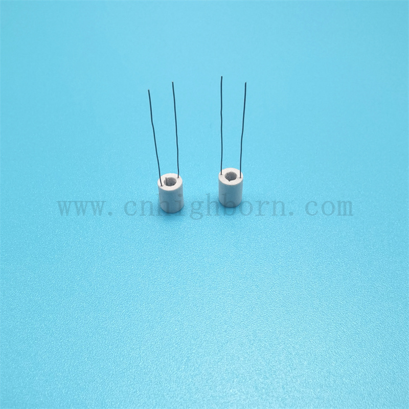
The design of the heating element dictates the initial heat distribution. Engineers utilize printed metallic films to maximize surface area contact with the ceramic substrate. Common geometries include "s-shape" traces, complex grid patterns, or honeycomb layouts. These designs stretch the heating element across the widest possible area of the ceramic block or cylinder. By covering the substrate edge-to-edge, the metallic film ensures comprehensive heat coverage. This geometry prevents cold zones at the edges of the core, maximizes the overall thermodynamic efficiency of the system, and ensures no liquid passes through unvaporized.
The physical geometry of the heating trace controls electrical resistance. Engineers map the resistance across the entire pattern to ensure uniform power distribution. If a trace narrows unintentionally due to poor printing tolerances, electrical resistance spikes in that specific area. This spike creates an immediate thermal hot spot, leading to localized burning. By maintaining strict dimensional tolerances during the screen-printing process, engineers keep electrical resistance flat across the entire film. This precise power distribution prevents isolated power surges and maintains a stable thermal baseline across the entire component.
The manufacturing process must bond the metallic film flawlessly to the ceramic substrate. Any separation between the metal and the ceramic creates an air gap. Air acts as a thermal insulator, disrupting heat transfer and causing the metallic film to overheat in that localized area. Manufacturers use advanced thick-film printing and high-temperature sintering to fuse the metal paste directly into the ceramic surface. This seamless adhesion guarantees immediate, unimpeded energy transfer from the heating trace into the porous matrix, ensuring the device responds instantly to user activation.
Standard forming techniques often leave density gradients within the ceramic body. These gradients cause uneven thermal conductivity, where one side of the core heats faster than the other. To achieve predictable thermal performance, manufacturers utilize advanced methods like hot isostatic pressing (HIP). HIP applies isobaric forming under high temperature and high pressure simultaneously. This process compresses the ceramic powder uniformly from all directions. It eliminates internal voids and ensures consistent structural density throughout the entire core. Uniform density guarantees that heat travels through the substrate at a constant, predictable rate.
Standard Hot Isostatic Pressing (HIP) Sequence:
Powder Preparation: Raw ceramic powder is milled to an exact particle size and mixed with organic binders and pore formers.
Green Body Casting: The slurry is cast or pressed into its initial, fragile shape (the green body).
Binder Burnout: The green body is heated slowly to remove organic binders, leaving behind the porous structure.
Pressurization: The component is placed in a HIP chamber and subjected to inert gas pressure (often argon) exceeding 100 MPa.
High-Temperature Sintering: While under pressure, the chamber is heated to temperatures often exceeding 1500°C to fuse the ceramic particles.
Controlled Cooling: The chamber is cooled at a strict rate to prevent thermal shock and micro-cracking in the finished core.
Precise control over sintering temperatures dictates the final integrity of the core. If temperatures fluctuate during the firing process, the ceramic develops structural micro-fractures. These fractures disrupt capillary action and alter thermal pathways, leading to unpredictable performance. Strict temperature control preserves the purity of the porous carbon or alumina base materials. Impurities act as thermal roadblocks, absorbing or deflecting heat unpredictably. Maintaining exact sintering profiles ensures structural perfection and material purity, which directly impacts heating consistency on the assembly line.
Maintaining tight manufacturing tolerances becomes exponentially harder at scale. Facilities must replicate exact pore sizes, trace geometries, and structural densities across millions of units per month. Simultaneously, they must adhere to strict safety standards. Heavy metal testing and RoHS compliance require rigorous material sourcing and process control. Any deviation in the metallic ink formulation or the ceramic powder can trigger compliance failures during third-party audits. Scaling production while maintaining thermal uniformity demands automated inspection systems, strict environmental controls on the factory floor, and uncompromising quality assurance protocols.
Thermal degradation curves highlight the stark differences between materials. Traditional cotton and wire coils degrade rapidly. Cotton burns easily when fluid levels drop, and metal wires oxidize after repeated heating cycles, shedding particles and altering resistance. A porous ceramic liquid atomizer resists oxidation and withstands extreme temperatures without structural damage. The ceramic matrix does not burn, even under dry conditions. This resistance to thermal degradation significantly extends the operational lifespan of the core, providing reliable performance long after traditional coils fail and require replacement.
Ceramic substrates possess a slightly higher thermal mass than bare wire coils. This mass can marginally increase the initial ramp-up time required to reach vaporization temperatures. However, this minor delay presents a worthwhile trade-off for product engineers. The superior, consistent flavor profile achieved through even heating far outweighs a fraction-of-a-second difference in ramp-up speed. The stable thermal environment prevents the harshness associated with wire coils, delivering high-fidelity flavor from the first draw to the last, ensuring a premium user experience.
Advanced manufacturing techniques like hot isostatic pressing and thick-film printing increase the initial production cost of ceramic cores compared to standard wire winding. Evaluators must weigh this upfront cost against the long-term return on investment. Ceramic cores drastically reduce failure rates on the assembly line and eliminate the warranty claims associated with burnt cotton. The delicate vapor production elevates the overall user experience, supporting premium product positioning in a crowded market. When factoring in lifespan, reliability, and brand reputation, the cost-to-performance ratio heavily favors ceramic technology.
Table 2: Performance Comparison of Atomization Technologies
| Performance Metric | Ceramic Atomization Core | Traditional Cotton & Wire Coil |
|---|---|---|
| Heat Distribution | Highly uniform across the substrate | Prone to localized hot spots |
| Dry Hit Resistance | Excellent (ceramic does not burn) | Poor (cotton chars easily) |
| Flavor Consistency | Stable throughout the product lifespan | Degrades as cotton and wire oxidize |
| Manufacturing Complexity | High (requires HIP and precise sintering) | Low (standard winding and wicking) |
| Vapor Texture | Fine, delicate, and consistent | Variable, often coarse |
The primary risk in manufacturing porous ceramics is inconsistent pore size across different batches. If a batch features pores that are too large, the resulting cores will leak fluid into the airflow chamber, ruining the device. If the pores are too small, the cores will choke and produce dry hits. Mitigating this risk requires strict auditing of supplier quality assurance processes. Manufacturers must utilize automated optical inspection (AOI) and fluid flow testing on every batch to verify porosity metrics before assembly begins. Bubble point testing is frequently used to confirm the maximum pore size in a given batch.
Ceramic materials possess high compressive strength but exhibit inherent brittleness under tensile or shear stress. Automated assembly lines can easily crack ceramic cores if insertion forces exceed material limits. Micro-cracking destroys the capillary matrix and compromises the heating trace, leading to immediate failure. Engineering teams must design shock-absorbing silicone gaskets to cushion the core within the housing. Assembly equipment requires precise force-feedback sensors to halt insertion before stress fractures occur, ensuring high yield rates during mass production.
High-temperature cycling accelerates material degradation. If manufacturers use substandard metallic inks or impure ceramic powders, the core may leach heavy metals into the vapor stream. Preventing this requires aggressive testing protocols. Facilities must utilize Inductively Coupled Plasma Mass Spectrometry (ICP-MS) to analyze vapor emissions for elements like lead, cadmium, arsenic, and mercury. This testing ensures that the metallic heating traces and ceramic substrates remain stable and do not release toxins under extreme thermal stress, maintaining strict compliance with global safety standards.
Standard Quality Control Protocol for Mass Production:
Raw Material Assay: Spectroscopic analysis of incoming ceramic powder to verify purity and absence of heavy metals.
Green Body Inspection: Dimensional checks before sintering to account for expected shrinkage rates.
Porosity Verification: Bubble point testing and scanning electron microscopy (SEM) on sample batches to confirm pore size distribution.
Resistance Testing: Automated probing of the metallic film to ensure electrical resistance falls within the specified tolerance window.
Emission Testing: ICP-MS analysis on vapor samples from finished prototypes to guarantee RoHS compliance.
Request detailed engineering samples and third-party emission test reports from prospective manufacturers to verify safety and performance claims.
Demand thermal imaging data during prototype evaluation to confirm the absence of localized hot spots across the heating trace.
Audit potential suppliers based on their specific sintering technology and automated quality control capabilities, prioritizing those utilizing hot isostatic pressing.
Establish strict acceptable variance limits for batch-to-batch pore size consistency before signing mass production agreements.
Implement force-feedback sensors on your automated assembly lines to prevent micro-cracking during core insertion.
A: A porous ceramic core utilizes a rigid, engineered matrix with uniform pore sizes. This structure maintains consistent capillary pressure, drawing liquid continuously to the heating surface. Unlike cotton, which suffers from uneven packing and burns when dry, ceramic maintains fluid saturation and withstands high temperatures without charring.
A: Pore size dictates the fluid flow rate. If pores are calibrated correctly to the liquid's viscosity, they supply the exact amount of fluid needed for continuous vaporization. Incorrect pore sizes lead to either flooding and leaks or fluid starvation, which reduces vapor output and causes dry hits.
A: Even heating ensures the entire liquid surface reaches the phase transition temperature simultaneously. This uniform thermodynamic environment produces smaller, tightly grouped aerosol particles. These fine particles deliver a smoother, more delicate vapor texture compared to the erratic particle sizes generated by uneven wire coils.
A: The "s-shape" geometry maximizes the surface area contact between the heating element and the ceramic substrate. This specific pattern stretches the heat source across the core, eliminating cold zones and ensuring edge-to-edge thermal coverage for highly efficient energy transfer.
A: Hot isostatic pressing applies high temperature and uniform pressure from all directions during forming. This process eliminates internal voids and creates a perfectly uniform structural density. Consistent density guarantees that heat travels through the ceramic substrate at a predictable, even rate.
A: High-quality ceramic cores mitigate leaching risks through pure material sourcing and high-temperature sintering. Reputable manufacturers verify this safety by subjecting their products to rigorous ICP-MS testing, ensuring the metallic traces and substrates remain stable and compliant with RoHS standards under thermal stress.