
Views: 0 Author: Site Editor Publish Time: 2026-09-23 Origin: Site


Premature circuit failure remains a persistent nightmare in electrical engineering. In the field, we rarely see boards fail because of a single, catastrophic lightning strike. Instead, they die slowly. They succumb to subtle, progressive component drift and improper thermal management in harsh operating environments. At the core of solving this thermal-electrical puzzle is a component that serves as the unsung backbone of modern power electronics: the thick film resistor.
A fatal oversight during the initial layout phase is selecting a resistor based solely on its nominal ohmic value at room temperature. For high-reliability applications, this rudimentary approach guarantees field failures. To ensure long-term stability and prevent thermal runaway, engineers must develop a practical understanding of how three critical metrics interact: Temperature Coefficient of Resistance (TCR), Tolerance, and Power Rating.
Looking at recent industry shifts, the aggressive transition toward 800V electric vehicle (EV) architectures and high-density 5G telecommunications has radically rewritten passive component requirements. Current market analyses indicate a massive, industry-wide departure from standard FR4 materials in power-dense modules. Engineers are now demanding substrates capable of enduring ambient temperatures exceeding 150°C while maintaining strict electrical tolerances. This broader industry trend underscores a harsh reality. Mastering the thermal-electrical relationship is no longer optional—it is a mandatory baseline for surviving in modern hardware design.
This comprehensive guide deconstructs these three technical factors. We will examine the foundational role of base materials, provide actionable layout advice, and explain how to design truly robust circuitry. By grasping the synergy between these specifications, procurement managers and hardware designers can make informed decisions that perfectly balance cost, precision, and systemic reliability.
Material is the First Line of Defense: The superior thermal conductivity of a ceramic base actively prevents localized overheating and subsequent dielectric breakdown.
TCR Dictates Long-Term Stability: The Temperature Coefficient of Resistance (TCR) determines exactly how much a resistor's value will drift under thermal stress. Lower TCR equates to predictable system performance.
Tolerance vs. Manufacturing Cost: While standard thick film technology offers broader initial tolerances, modern active laser trimming achieves precision tuning suitable for strict industrial feedback loops.
Derating is Non-Negotiable: Properly matching the power rating to the heat dissipation capabilities of the board prevents catastrophic failure, especially in high-voltage transient applications.
The Reliability Triangle: TCR, tolerance, and power rating do not operate in isolation. A shift in operating temperature dynamically impacts both power handling and initial resistance accuracy.
To specify the correct component for a demanding environment, you must first understand its physical construction. The reliability of a printed resistor is heavily dependent on the raw base materials utilized during manufacturing.
A thick film circuit is manufactured through a highly controlled, high-temperature additive process. It begins by screen-printing a specifically formulated resistive paste onto a rigid base material. This paste—a mixture of glass frit, organic solvents, and metal oxides like ruthenium oxide (RuO2)—is then fired in a conveyor furnace. Reaching temperatures often exceeding 850°C, this firing process burns off the solvents and permanently fuses the paste to the base.
The resulting solid-state resistive layer generally measures between 10 to 50 micrometers in thickness. Consequently, this robust physical volume makes the component significantly more resilient against electrical surges and mechanical stress than delicate thin-film alternatives.
The foundation of this technology relies entirely on the base material onto which the paste is printed. In the majority of industrial, aerospace, and automotive sectors, 96% Alumina (Al2O3) remains the undisputed gold standard.
When comparing a ceramic circuit board to standard FR4 (fiberglass-reinforced epoxy) used in conventional PCBs, the differences in physical properties dictate their distinct use cases. Alumina offers exceptional mechanical rigidity and superior dielectric properties, providing excellent electrical insulation (typically greater than 15 kV/mm). More importantly, it possesses unmatched thermal conductivity.
| Parameter | Standard FR4 | 96% Alumina (Al2O3) |
|---|---|---|
| Thermal Conductivity | ~0.25 W/m·K | 24 - 25 W/m·K |
| Max Operating Temp (Base) | 130°C - 140°C | > 800°C |
| Dielectric Strength | ~10 kV/mm | > 15 kV/mm |
| Application Suitability | Low power, logic circuits | High voltage, EV inverters, harsh environments |
Because its thermal conductivity hovers around 24-25 W/m·K—nearly 100 times greater than that of standard FR4—the ceramic base acts as a highly efficient, built-in heat sink. It aggressively pulls thermal energy away from the active resistive element and distributes it evenly. This action actively prevents the formation of micro-hotspots that would otherwise degrade the paste and cause resistance drift.
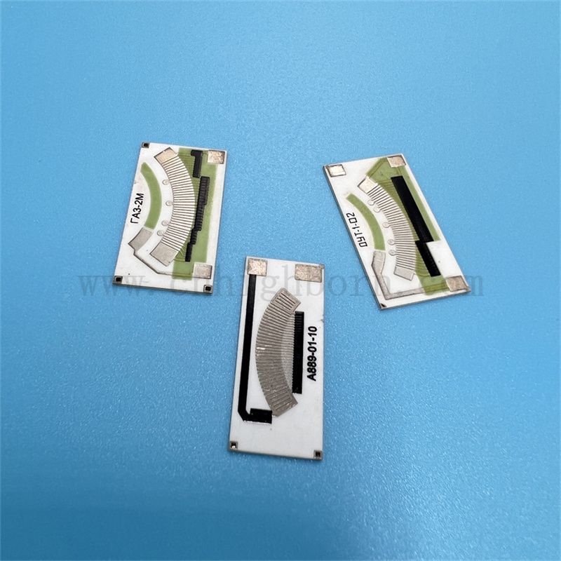
Thermal management addresses only half of the engineering equation. Designers must also account for how the resistor behaves electrically when its internal temperature inevitably fluctuates under load.
The Temperature Coefficient of Resistance (TCR) measures the relative change in a resistor's ohmic value as the operational temperature rises and falls. Expressed in parts per million per degree Celsius (ppm/°C), this metric is vital for precision. How does this look in practice?
If a 10 kΩ resistor features a TCR of +100 ppm/°C, its resistance will increase by 1 ohm for every single degree Celsius change. If the board heats up by 80°C, the resistance shifts by 80 ohms. In a highly sensitive analog voltage divider, that specific drift is often enough to trigger a false fault code or shut down a motor controller entirely.
Thermal drift is an unavoidable reality governed by the atomic structure of the resistive paste. As electrical current passes through the thick film layer, it generates internal Joule heating (I²R losses). If an alumina resistor substrate is not sized correctly to dissipate this heat, the temperature of the resistive element spikes rapidly.
Furthermore, this localized temperature rise agitates the atoms within the film. This atomic agitation scatters the electrons flowing through the material, thereby increasing the overall resistance. If the resistance drifts significantly out of specification, it leads to inaccurate sensor readings and, in worst-case scenarios, total system failure.
Tolerance represents the second pillar of resistor specification. It defines the permissible deviation from the specified nominal resistance value, measured strictly at room temperature (25°C) before any operational stress is applied.
When a procurement manager sources a 1,000Ω component with a ±5% tolerance, the actual resistance straight off the reel will measure anywhere between 950Ω and 1,050Ω. Specifying a tighter tolerance—such as ±0.1%—exponentially increases manufacturing costs and lowers production yields. Therefore, engineering teams must objectively assess whether their feedback loops truly require extreme precision, or if a standard ±1% tolerance will suffice for the application.
Screen-printing and high-temperature firing inherently produce slight resistance variations. How do manufacturers fix this? They rely on active laser trimming to bridge the precision gap.
During this automated process, specialized equipment measures the resistance of the circuit in real-time. A highly focused laser beam then makes microscopic cuts—such as "L-cuts" or "plunge cuts"—into the resistive film. By removing conductive material, the laser forces the electrical current to travel a longer, narrower path. This effectively increases the total resistance until it hits the exact target value, allowing thick film components to achieve impressive ±1% or even ±0.5% tolerances.
The third critical metric, Power Rating, dictates the maximum amount of continuous energy (in watts) a resistor can safely dissipate without exceeding its maximum allowable operating temperature.
The relationship between power, voltage, and resistance is fundamentally defined by Ohm's Law (P=V²/R). In applications requiring a high voltage resistor, such as medical defibrillators or grid infrastructure, even a marginal increase in voltage results in an exponential spike in dissipated power and generated heat.
Thick film technology is uniquely equipped for these harsh scenarios. Because the physical volume of the resistive element is larger and denser than that of thin film, it provides a higher thermal mass. This allows the component to absorb and distribute sudden, massive electrical surges (pulse loads) without experiencing catastrophic dielectric breakdown.
A fatal assumption in circuit design is believing a component will handle its maximum power rating under all environmental conditions. It will not. To guarantee long-term reliability, designers must rigorously apply derating curves provided by the manufacturer.
Specifically, a standard derating curve plots allowable power dissipation against ambient temperature. Typically, a thick film component can operate at 100% of its rated power up to an ambient temperature of 70°C. Beyond that threshold, the allowable power decreases linearly, often reaching 0 watts at 155°C. If you are designing a power supply intended for a 100°C environment, you must calculate the derated limit and select a component with a significantly higher baseline power rating to compensate.
Evaluating component specifications in isolation is a common pitfall. In practice, TCR, Tolerance, and Power Rating form an interconnected "Reliability Triangle." Altering one variable dynamically impacts the performance of the others.
Consider a scenario where an engineer specifies a resistor with a tight ±1% tolerance but pushes the component to 95% of its maximum Power Rating. Operating near this upper limit generates significant internal heat. Consequently, this temperature rise immediately triggers the TCR effect.
If the TCR is ±100 ppm/°C and the temperature rises by 80°C, the resistance drifts by an additional 0.8%. When this thermal drift is compounded with the initial ±1% manufacturing tolerance, the total operational tolerance expands to ±1.8%. The component has effectively drifted out of its intended precision window simply because the power rating and TCR were not evaluated synergistically.
In the context of electric vehicle (EV) motor inverters, space is at a premium, ambient temperatures routinely exceed 105°C, and electrical noise is severe. An engineer designing the voltage sensing circuit cannot rely on standard FR4-based components.
By selecting a ceramic-based solution, the designer leverages the material's thermal conductivity to survive the ambient heat. They apply strict derating rules based on the 105°C environment, selecting a higher-wattage component than theoretically necessary. Finally, they account for the known TCR drift in their software algorithms, ensuring the microcontrollers receive accurate data despite thermal fluctuations. Balancing this triangle prevents inverter failure and guarantees vehicle safety.
Selecting a robust component is only half the battle. The physical layout of the printed circuit board ultimately dictates how well that component will perform in the field.
To maximize the power rating and minimize TCR-induced drift, PCB layout designers must focus heavily on thermal pathways. Connecting the resistor to wide, heavy copper traces (e.g., 2 oz or 3 oz copper) provides excellent thermal wicking, drawing heat directly away from the component terminals.
In addition, placing thermal vias directly underneath or adjacent to the component pads allows heat to transfer efficiently through the board to internal ground planes or external chassis heat sinks. High-power components should also be adequately spaced apart to prevent overlapping thermal profiles, which can create dangerous localized hot spots.
For procurement managers and lead engineers at the final decision stage, the focus shifts from theoretical design to practical sourcing. The reliability of the end product is inextricably linked to the quality control standards of the manufacturer.
When standard catalog parts cannot meet the thermal or electrical demands of a project, partnering with a specialized manufacturer becomes imperative. If you are dealing with odd form factors or extreme pulse loads, you will likely need to source a custom resistor substrate. Key indicators of a reliable supplier include:
Material Purity: The supplier must guarantee the purity of their alumina (minimum 96%) to ensure consistent 24 W/m·K thermal conductivity across all production batches.
Precision Trimming: Look for manufacturers utilizing state-of-the-art laser trimming systems capable of executing complex geometries (±1% or ±0.5% tolerances).
Custom Thickness: The ability to provide custom ceramic thicknesses (e.g., 0.635mm, 1.0mm, or 2.0mm) to handle specific high-voltage dielectric requirements.
Verifiable Data: Reliable suppliers provide comprehensive testing documentation, including environmental stress data, TCR validation across multiple temperature ranges, and strict derating curves.
Designing a reliable circuit requires a holistic, engineering-first approach. It goes far beyond simply choosing a resistive paste with the correct ohmic value. The thermal properties of the ceramic base, the TCR, the initial tolerance, and the power rating must all work in perfect harmony.
Over-specifying your components wastes valuable project budget, while under-specifying leads to dangerous, costly field failures. Proper thermal management, combined with a strict adherence to derating curves, ensures perfect component selection. When off-the-shelf components compromise your design, it is time to upgrade your base materials. Whether you are developing 800V EV inverters, high-frequency telecom modules, or industrial power supplies, explore high-performance custom solutions from Highborn at https://www.cnhighborn.com to find the exact ceramic substrate that matches your rigorous specifications.
The typical TCR of a thick film resistor generally ranges from ±50 ppm/°C to ±200 ppm/°C, depending on the specific resistance value and the chemical composition of the paste used. While this is higher than thin film alternatives, it remains highly stable and perfectly adequate for the vast majority of power electronics and rugged industrial applications.
Yes. Thick film technology is exceptionally well-suited for high voltage applications. Because the resistive layer is physically thicker and denser than thin film, it can withstand high electrical surges, transient spikes, and continuous high-voltage stress without experiencing dielectric breakdown or vaporization.
Alumina is preferred primarily because it offers significantly higher thermal conductivity (typically 24-25 W/m·K) compared to standard FR4 epoxy glass (around 0.25 W/m·K). This immense difference allows the ceramic board to dissipate heat rapidly, preventing localized hot spots and maintaining a stable power rating under heavy electrical loads.
Initial manufacturing tolerance is strictly measured at room temperature (usually 25°C). As the operating temperature of the circuit increases due to ambient environmental heat or internal power dissipation, the Temperature Coefficient of Resistance (TCR) dictates exactly how much the resistance will drift away from that initial factory tolerance.
Absolutely. Specialized component manufacturers can design custom substrates by altering the physical size, thickness, and material composition of the ceramic base. Adjusting the geometry or increasing the thickness allows the component to meet precise thermal dissipation and electrical power requirements for unique projects.
Thick film resistors are made by screen-printing a conductive paste onto a substrate, resulting in a thicker, more rugged layer (10-50 microns) that is ideal for high power and surge handling. Thin film resistors are created via vacuum deposition, creating a very thin layer that offers tighter tolerances and lower TCR, but is far more susceptible to damage from power surges and harsh environments.
Resistor derating is calculated using the manufacturer's provided derating curve. First, identify the maximum ambient temperature of your specific application. If it exceeds the 100% power threshold (typically 70°C), follow the linear slope down to find the allowable percentage of the rated power. For example, in a 105°C environment, a resistor nominally rated for 10W might only be safely operated at 5W.