
Views: 0 Author: Site Editor Publish Time: 2026-08-16 Origin: Site


Precision agriculture and high-value horticulture require irrigation systems that respond to actual plant demand, rather than arbitrary timer schedules. Traditional plastic drip emitters rely on fixed system pressure, electronic controllers, and mechanical diaphragms. This often results in over-watering, runoff, or localized dry spots due to fluctuating environmental conditions that static timers cannot account for. When a sudden heatwave hits, a static timer pushes the exact same volume of water as it does on a cool, overcast day. This mismatch damages root zones and wastes valuable resources. We introduce the physical mechanics of porous ceramics as a demand-responsive alternative. Detail how shifting from pressure-forced delivery to tension-driven delivery changes system design, water efficiency, and crop yield outcomes. You will learn how leveraging natural soil suction eliminates the guesswork from your watering cycles and creates a highly resilient growing environment for sensitive crops.
Tension-Driven Flow: Unlike standard emitters, a ceramic irrigation dripper regulates water release based on soil matric potential (suction), stopping flow automatically when soil reaches field capacity.
Low-Pressure Optimization: Ceramic systems operate efficiently under ultra-low pressure or gravity-fed setups, reducing energy costs and infrastructure requirements.
Filtration is Critical: The microporous nature of ceramics makes them highly susceptible to mineral scaling and biological clogging, necessitating stringent pre-filtration and maintenance protocols.
Simplified Automation: By utilizing the soil's natural suction to regulate flow, ceramic systems can often eliminate the need for complex electronic drip controllers and automatic valves.
Best Use Cases: Ideal for controlled environments, containerized high-value crops, and off-grid gravity systems where water conservation and precise moisture consistency outweigh initial setup complexity.
Establishing the baseline physics helps operators configure their watering networks correctly. A successful irrigation system delivers water exactly when roots actively seek it. It stops delivering water before the soil becomes waterlogged. We evaluate success by measuring how closely the delivery rate matches the plant's actual transpiration rate in real-time. Understanding fluid dynamics at the microscopic level prevents catastrophic design failures in the field.
Dry soil acts like a dense, rigid sponge. It creates a microscopic vacuum within its structure. This vacuum pulls water through the micropores of the ceramic material. Agronomists call this force matric potential. The drier the surrounding soil becomes, the stronger this vacuum pulls against the water source. Water molecules possess high cohesion and adhesion properties. They bind tightly to each other and to the surrounding soil particles. This capillary action physically drags water out of the ceramic matrix and directly into the active root zone.
You can compare this mechanism directly to the function of a soil tensiometer ceramic tube. A tensiometer measures this exact soil suction force. It determines moisture levels by reading the vacuum pressure on a mechanical gauge. The irrigation dripper utilizes the exact same physical principle. Instead of just reading the pressure, it uses the pressure to physically release water from a holding reservoir. This creates a highly efficient, natural feedback loop.
The plant transpires during the day, removing moisture from the immediate soil profile.
The soil dries out, increasing the matric potential and creating a localized vacuum.
The suction pulls water through the microscopic ceramic pores to replace the lost moisture.
The soil moisture increases, satisfying the plant's immediate demand.
The tension decreases as the soil saturates, naturally slowing the water flow.
The flow halts completely once the soil reaches field capacity, preventing any runoff.
The manufacturing process dictates the exact micron size of the ceramic pores. Firing temperatures and specific clay compositions determine the internal structure of the material. Higher firing temperatures generally create tighter, more restrictive matrices that allow less water to pass through. Hydraulic conductivity depends entirely on these micron-sized pathways remaining clear. Pore size correlates directly to the maximum possible flow rate under heavy soil tension.
Soil type heavily influences system performance. Sandy soils drain very quickly and exhibit exceptionally low capillary pull. They require different pore structures than heavy clay soils to function properly. Clay retains water much longer and generates entirely different tension dynamics at the soil-water interface. Loam provides the best balance, offering strong capillary action without the heavy waterlogging risks associated with pure clay.
Soil Type and Capillary Action Dynamics
| Soil Classification | Capillary Pull Strength | Drainage Rate | Compatibility with Ceramics |
|---|---|---|---|
| Heavy Clay | Very High | Very Slow | Excellent (Requires low-flow ceramics) |
| Silty Loam | High | Moderate | Optimal (Balanced tension and flow) |
| Sandy Loam | Moderate | Fast | Good (Requires closer emitter spacing) |
| Coarse Sand | Low | Very Fast | Poor (Water drops vertically, bypassing roots) |
Commercial growers usually choose between tension-driven ceramics and industry-standard pressure-compensating (PC) plastic drip systems. Each approach utilizes fundamentally different mechanics to regulate water delivery. Understanding these mechanical differences prevents costly design errors during the initial installation phase. You cannot treat a ceramic system like a standard plastic drip line.
Standard PC drippers rely on internal silicone diaphragms. These flexible diaphragms move physically as line pressure fluctuates across the field. They restrict or open the internal flow path to maintain a set discharge rate regardless of elevation changes. Manufacturers engineer them to deliver specific volumes, typically between 0.5 to 4 Gallons Per Hour. This constant diaphragm movement provides a distinct mechanical self-cleaning action. It actively pushes out small debris and prevents immediate clogging. The turbulent flow path inside the plastic emitter keeps particulate matter moving constantly.
When you install a Ceramic Irrigation Dripper, you completely eliminate moving parts from the delivery point. They rely entirely on the static soil-water interface for regulation. They possess absolutely no mechanical self-cleaning capabilities. They depend solely on organic soil tension to pull water through their tortuous internal pathways. The flow remains laminar rather than turbulent. This makes them highly sensitive to internal obstructions from minerals or biological matter.
Calculating total water usage presents unique challenges with ceramics. Standard plastic systems express discharge predictably. You measure Gallons Per Minute per 100 feet of tubing. You know exactly how much water leaves the tank per hour based on the pump pressure. Ceramic flow rates vary constantly throughout the day. They change based on real-time plant transpiration, ambient humidity, and soil evaporation. You lose strict volumetric control over the system. However, you gain optimal, continuous soil moisture consistency. Plants experience significantly less drought stress between watering cycles because the soil never fully dries out.
Emitter Technology Specifications
| Specification | Pressure-Compensating Plastic | Porous Ceramic |
|---|---|---|
| Regulation Mechanism | Silicone Diaphragm (Mechanical) | Matric Potential (Organic Tension) |
| Flow Predictability | Fixed (e.g., 0.5 - 4 GPH) | Variable (Demand-based) |
| Self-Cleaning Action | Yes (Diaphragm movement) | No (Requires manual maintenance) |
| Operating Pressure Range | 6 psi to 45 psi | 0.5 psi to 3 psi (Gravity-fed) |
| Ideal Soil Application | Universal application | Loam and Clay (High capillary action) |
| Clogging Susceptibility | Low to Moderate | High (Requires pristine water) |
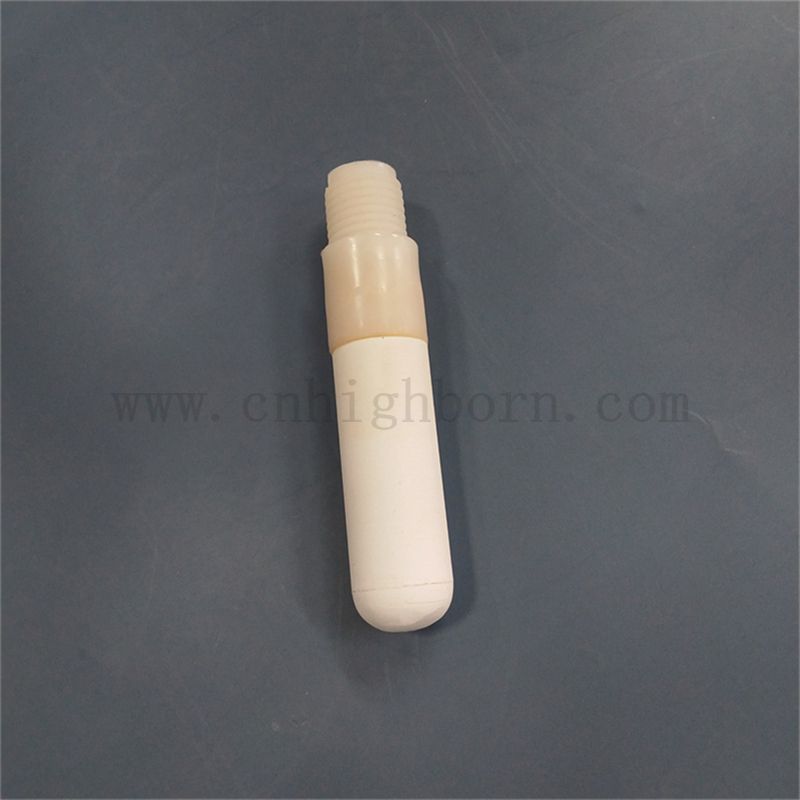
Deploying ceramic systems at scale demands specific infrastructure planning. You cannot simply swap plastic emitters for ceramic ones on an existing high-pressure line. The entire delivery network requires fundamental re-engineering to accommodate tension-driven physics. The transition affects everything from your main pump station down to the micro-tubing at the plant base.
Standard drip irrigation requires electronic drip controllers. These controllers manage automatic solenoid valves across different irrigation zones. They dictate opening and closing times based on arbitrary human schedules or basic weather data. Integrating a porous ceramic irrigation probe shifts the control mechanism directly to the soil itself. Growers can entirely bypass complex electronic timers. The system delivers water continuously from a central reservoir. The soil acts as the ultimate sensor and valve combined, pulling water only when necessary.
Traditional drip tubing networks require specific operating pressures to function correctly. Typical operating pressures range from 12 psi to 45 psi. If pressure drops below the minimum threshold, the silicone diaphragms fail to open, and the plants receive no water. Ceramic probes require ultra-low pressure environments. They often function perfectly on less than 3 psi. Simple gravity heads work exceptionally well for these setups. You only need to place a reservoir slightly above the plant canopy to create sufficient head pressure for the entire network.
This pressure difference impacts pump sizing significantly. Energy consumption drops drastically when you eliminate high-pressure centrifugal pumps from your operation. You transition from standard rigid poly-tubing to flexible micro-tubing networks. Micro-tubing handles low pressure easily and routes cleanly around containerized plants without kinking.
Scalability in commercial applications presents logistical hurdles that operators must plan for. Deploying ceramic probes across large outdoor acreage remains difficult due to the manual labor required. Greenhouse and container environments suit them much better. Installing individual probes at the root zone takes considerable time and precision.
Excavate the root zone carefully to avoid damaging existing feeder roots.
Soak the ceramic components in clean water for 24 hours prior to installation to purge trapped air.
Insert the probe into the soil, ensuring zero air gaps exist around the ceramic surface.
Backfill with a slurry of native soil to guarantee immediate capillary contact.
Connect the flexible micro-tubing to the main low-pressure distribution line.
Monitor the reservoir drop rate over the first week to establish a baseline consumption metric.
Operators must understand the operational hazards associated with porous ceramics. You must engineer your system to mitigate these specific risks before planting. Ignoring water quality or maintenance schedules will result in rapid system failure and potential crop loss.
Mineral buildup poses the absolute biggest threat to ceramic longevity. Calcium carbonate, magnesium, and iron precipitate naturally inside the micropores as water flows through. Hard water permanently reduces hydraulic conductivity over time. The pores literally clog from the inside out, choking off the water supply. A ceramic emitter cannot flush these minerals away mechanically like a plastic dripper. You must conduct comprehensive water testing prior to adoption. If your water shows high hardness levels, you must implement strict acid-washing routines. Mild acid dissolves the mineral scale and reopens the microscopic pathways, restoring original flow rates.
Biological clogging also occurs frequently in low-pressure systems. Algae and bacterial biofilms form rapidly on the damp porous surface of the ceramic. They create a slimy, impermeable barrier that blocks water transmission into the soil. Mitigation involves installing dedicated UV filtration on your main water line to kill pathogens before they enter the tubing. You must flush distribution lines regularly to remove stagnant water. Implement light-blocking system designs wherever possible. Use opaque tubing and covered reservoirs to prevent algae from photosynthesizing inside the delivery network.
Physical fragility matters during installation and seasonal crop rotation. Heavy-duty plastics resist impact, tractor tires, and rough handling by field crews. Ceramics shatter if dropped on hard surfaces or struck with a trowel. Workers must handle them carefully during seasonal changeovers to avoid micro-fractures that ruin the tension seal.
Frost damage presents a severe, unavoidable risk in colder climates. Freezing water expands violently inside the rigid ceramic matrix. This expansion cracks the material instantly, destroying the probe completely. You must drain the system completely before the first freeze hits. Better yet, remove the probes from the soil entirely and store them indoors during winter months.
Preventative Maintenance Schedule
| Maintenance Task | Frequency | Execution Method |
|---|---|---|
| System Flushing | Bi-weekly | Open end-caps on main lines to purge stagnant water and loose debris. |
| Acid Washing | Bi-annually | Soak ceramic probes in a 5% agricultural vinegar solution for 12 hours. |
| UV Bulb Replacement | Annually | Replace inline UV sterilizer bulbs to maintain biological control. |
| Winterization | Pre-freeze | Extract probes, dry completely, and store in a climate-controlled facility. |
Conduct a comprehensive water quality test focusing specifically on calcium hardness and suspended solids before purchasing any ceramic components.
Run a small-scale pilot test with five to ten plants to measure actual flow rates and tension dynamics in your specific soil media.
Install a dedicated 150-mesh screen filter and an inline UV sterilizer immediately after your main water reservoir to prevent internal clogging.
Designate a safe, dry storage protocol for all ceramic components during winter months to prevent catastrophic frost damage.
A: Flow rate remains highly variable. Soil tension and the specific porosity of the ceramic dictate the water release. It does not follow a fixed standard found in plastic emitters. The drier the soil becomes, the faster the water flows through the ceramic matrix. You must measure the drop in your central reservoir over time to calculate actual consumption.
A: Generally, no. The ceramic material releases water based entirely on soil suction. The soil itself acts as the controller. This natural feedback loop eliminates the need for automatic valves and complex electronic timers in most gravity-fed setups. The system regulates itself based on real-time plant demand.
A: You face significant risks of salt buildup. Synthetic fertilizers can clog the microscopic pores very quickly as salts precipitate out of the solution. We recommend using highly soluble, clean nutrient lines if you must fertigate. Alternatively, apply granular fertilizers directly to the soil to protect the ceramic pores from internal scaling.
A: Standard maintenance involves soaking the components in mild acid solutions. Vinegar or specialized agricultural cleaners dissolve the mineral scale effectively without damaging the material. Gently scrub the exterior surface with a soft brush. Follow this by thorough flushing with clean water to remove all dissolved debris and residual acid.
A: Many systems require near-zero pressure. They operate effectively on simple gravity feeds. You only need to place a water reservoir a few feet above the plant canopy to generate enough head pressure. This remains well below the 12 to 45 psi required to open standard pressure-compensating plastic drip tubing.
A: Sandy soil exhibits very low capillary action. It pulls water much less effectively than clay or loam. This interacts poorly with standard ceramic pores, often causing water to drop straight down past the root zone. You require drippers featuring higher hydraulic conductivity and closer placement strategies to achieve proper moisture distribution in sand.