
Views: 0 Author: Site Editor Publish Time: 2026-08-11 Origin: Site


The accuracy of any working electrode measurement depends entirely on the absolute stability of the reference half-cell. Potential drift introduces severe operational risks. You get compromised analytical data, failed quality control batches, and wasted laboratory hours troubleshooting false positives. These issues frequently stem from degraded or improperly specified electrodes interacting poorly with complex sample matrices. Mitigating these risks requires understanding the thermodynamic mechanics, junction materials, and environmental limitations inherent to the silver/silver chloride system. Evaluating, selecting, and maintaining the correct electrode configuration for specific analytical applications ensures data integrity. By mastering the physical and chemical principles governing these devices, you eliminate erratic readings and secure reproducible, highly accurate electrochemical measurements across diverse testing environments.
Thermodynamic Equilibrium: An Ag AgCl reference electrode achieves a constant potential through a reversible redox reaction, governed strictly by the sustained activity of chloride ions in the internal electrolyte.
Junction Integrity: The physical interface—often a porous ceramic salt bridge—is critical for maintaining electrical continuity while preventing sample contamination and minimizing liquid junction potentials.
Environmental Vulnerabilities: Temperature fluctuations and sample matrices containing sulfides or heavy metals directly impact stability, necessitating specific configurations like double-junction designs.
Lifecycle Management: Consistent performance requires rigorous maintenance protocols, including proper storage solutions, regular electrolyte replenishment, and verification against a master reference electrode.
In a standard three-electrode setup, the Reference Electrode performs a singular function. It completes the electrical circuit while providing a stable, known ground voltage. This baseline voltage acts as the anchor point against which the working electrode's potential is continuously measured and controlled. Without a stable reference point, the potentiostat cannot accurately apply or measure the voltage necessary to drive the desired electrochemical reactions at the working electrode interface. The reference half-cell must pass minimal current to prevent polarization. This ensures its potential remains constant regardless of the dynamic changes occurring elsewhere in the cell.
Potential stability stands as the ultimate evaluation metric for any reference system. Even millivolt-level drift can completely invalidate sensitive analytical techniques. In cyclic voltammetry, a shifting reference potential skews peak positions. This leads to incorrect identification of redox species or inaccurate calculations of reaction kinetics. During potentiometric titrations or pH measurements, baseline drift translates directly into measurement error. This can cause entire batches of product to fail quality specifications. In long-term corrosion testing, an unstable reference obscures the subtle voltage shifts that indicate the onset of pitting or passivation. Maintaining absolute stability is a fundamental requirement for generating valid electrochemical data.
The core of the Ag AgCl reference electrode relies on a solid-state interface governed by a reversible redox pair. A silver wire coated with a solid layer of silver chloride sits immersed in an electrolyte solution containing a known concentration of chloride ions. This metal-ion equilibrium ensures a constant exchange of charge across the interface. The reaction proceeds in both directions at equal rates when no external current is applied. Because the silver and silver chloride exist as solid phases with unit activity, they do not alter the chemical composition of the surrounding electrolyte. This allows the system to maintain a steady state indefinitely under ideal conditions.
The Nernst equation mathematically dictates the behavior of this system. It reveals that the electrode's potential is exclusively dependent on the activity of the chloride ions in the internal filling solution. Maintaining a saturated or precisely known concentration of potassium chloride (KCl) or sodium chloride (NaCl) is the non-negotiable factor in preventing potential shift. If the chloride concentration changes due to evaporation, dilution, or contamination, the equilibrium shifts. The potential drifts accordingly. This strict thermodynamic dependence demands rigorous control over the internal electrolyte composition.
Operators must choose between saturated and unsaturated filling solutions. Each presents distinct thermodynamic profiles. Saturated KCl solutions offer the advantage of maintaining a constant potential even if some water evaporates. Excess solid salt simply dissolves to maintain saturation. However, saturated solutions are highly prone to temperature-induced precipitation. A drop in temperature causes salt crystals to form, which can clog the junction. Conversely, unsaturated solutions, such as 3M or 3.5M KCl, provide superior temperature stability. They resist crystallization at lower temperatures. The trade-off is their sensitivity to evaporation. Any loss of water increases the chloride concentration, causing an immediate and permanent shift in the reference potential.
| Electrolyte Type | Evaporation Resistance | Temperature Stability | Primary Risk Factor |
|---|---|---|---|
| Saturated KCl | High (excess salt dissolves) | Low (precipitates easily) | Junction clogging from salt crystals |
| 3M / 3.5M KCl | Low (concentration shifts) | High (resists freezing/crystallization) | Potential drift from water loss |
When evaluating the Ag/AgCl system against historical alternatives, its dominance in modern laboratories becomes clear. The Calomel electrode relies on a mercury/mercury chloride equilibrium. While highly stable, it has been largely phased out due to severe environmental and health hazards associated with mercury toxicity. The Standard Hydrogen Electrode (SHE) serves as the theoretical zero-volt baseline for all electrochemical potentials. However, it requires bubbling highly flammable hydrogen gas over a platinized platinum electrode immersed in strong acid. This makes the SHE entirely impractical for daily laboratory or field use. The Ag/AgCl system provides the optimal balance of safety, practical usability, and thermodynamic stability.
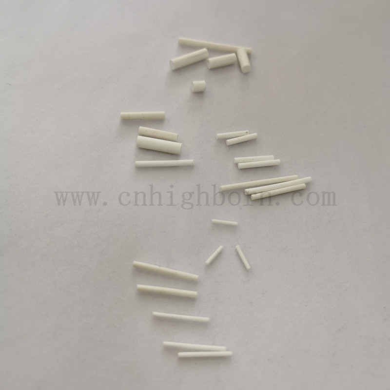
The physical interface between the internal electrolyte and the external sample is managed by the junction. This often takes the form of a porous ceramic salt bridge. This component performs a delicate balancing act. It must allow a controlled, ultra-slow leak of the internal electrolyte into the sample to establish ionic conductivity. This completes the electrical circuit. Simultaneously, it must restrict bulk fluid exchange to prevent the sample from rushing in and contaminating the internal redox environment. The microscopic pores of the ceramic material create a tortuous path that facilitates ion migration while minimizing physical mixing.
Selecting the correct junction material requires matching the physical properties of the junction to the characteristics of the sample matrix. A standard reference electrode ceramic junction excels in clean aqueous solutions. It provides a steady, predictable flow rate. However, in dirty, turbid, or particulate-heavy samples, ceramic pores quickly clog. In these environments, porous PTFE (Teflon) junctions are preferred. Their non-stick surface resists fouling and repels particulates. For high-viscosity environments or samples that tend to coat surfaces, a glass sleeve junction offers a high flow rate and an easily cleanable interface. Fiber junctions provide a low-cost, general-purpose alternative for basic aqueous testing but lack the durability of ceramic or PTFE.
| Junction Material | Best Application Environment | Flow Rate Characteristics | Maintenance Needs |
|---|---|---|---|
| Porous Ceramic | Clean aqueous solutions | Slow, highly controlled | Requires regular soaking to prevent dry-out |
| PTFE (Teflon) | Dirty, particulate-heavy samples | Moderate, resists clogging | Wipe clean, highly durable |
| Glass Sleeve | High viscosity, oils, emulsions | High, adjustable flow | Frequent flushing and physical cleaning |
| Fiber / Wick | General purpose, low-cost testing | Moderate to fast | Prone to degradation, replace frequently |
Managing liquid junction potentials and mitigating clogging risks are daily operational challenges. A liquid junction potential arises when ions from the internal electrolyte diffuse into the sample at different rates due to varying mobilities. Potassium and chloride ions have very similar mobilities, which is why KCl is the preferred electrolyte. If the junction clogs, this potential becomes erratic. Clogging frequently occurs when the internal electrolyte interacts with incompatible sample ions. If a saturated KCl electrolyte meets a sample containing high levels of silver or lead, insoluble chlorides precipitate directly within the junction pores. Evaluating junction flow rates based on the target application's viscosity and particulate load prevents these blockages.
Choosing between single-junction and double-junction configurations is the first decision in electrode selection. A single-junction design features one porous interface separating the internal Ag/AgCl element and its surrounding electrolyte directly from the sample. This works perfectly for benign aqueous solutions. A double-junction design mitigates contamination by isolating the inner Ag/AgCl element behind a second, customizable electrolyte chamber. The outer chamber interacts with the sample, shielding the delicate inner equilibrium from reactive species. This configuration is mandatory when testing samples that would otherwise poison the silver wire or precipitate within a single junction.
Aqueous and non-aqueous solvents present entirely different challenges. Standard aqueous reference electrodes cannot be directly immersed in non-aqueous or organic solvents. Doing so introduces massive, unstable liquid junction potentials at the aqueous-organic interface. It often causes immediate salt precipitation as the aqueous KCl is insoluble in most organics, instantly clogging the frit. To navigate this, laboratories utilize double-junction configurations where the outer chamber is filled with an electrolyte compatible with the organic sample. Alternatively, pseudo-reference electrodes are used in non-aqueous systems, though their potential must be calibrated internally using a known redox standard like ferrocene.
Temperature dependence and hysteresis profiles must be factored into the experimental design. The thermodynamic reality is that the potential of an Ag/AgCl system changes predictably with temperature. This is governed by the temperature coefficient of the Nernst equation. If an electrode is moved from a hot sample to a cold sample, it experiences thermal hysteresis. This is a lag in returning to a stable potential as the internal components slowly reach thermal equilibrium. Operators must allow sufficient equilibration time before recording measurements to avoid transient thermal errors.
Chemical incompatibilities rapidly destroy the stability of the reference half-cell. Specific sample matrices trigger poisoning mechanisms that permanently alter the internal redox environment. When exposed to sulfides, proteins, cyanides, or heavy metal ions, the silver chloride coating on the internal wire undergoes detrimental chemical reactions. Sulfides react instantly with silver to form silver sulfide. This is a highly insoluble black precipitate that coats the wire and alters the exchange current density, shifting the potential unpredictably. Proteins can denature and bind to the porous frit, completely blocking ionic flow and breaking the electrical circuit.
Electrolyte dilution represents another major vulnerability. If the hydrostatic pressure inside the electrode falls below the pressure of the sample, sample fluid will intrude through the junction. This intrusion dilutes the internal chloride ion concentration. Any change in chloride activity results in a predictable but highly problematic shift in the reference potential. Similarly, if the fill hole is left open during long-term storage, water evaporates. This concentrates the chloride ions and causes a corresponding potential drift. Maintaining the precise chemical composition of the internal filling solution is paramount.
Proper filling and electrolyte replenishment protocols dictate the lifespan of the device. The internal filling solution must be maintained at an optimal level to ensure proper hydrostatic head pressure. This forces a slow outward flow of electrolyte and prevents sample intrusion. Operators must strictly avoid trapping air bubbles near the internal silver wire or against the inner surface of the ceramic frit. Bubbles break electrical continuity and cause erratic, noisy signals. During active measurements, the fill hole must remain open to allow atmospheric pressure to push the electrolyte through the junction.
Storage protocols directly impact junction integrity and prevent dry-out. Short-term storage requires immersing the junction in a solution that exactly matches the internal electrolyte. This prevents osmotic pressure imbalances that would otherwise drive water into or out of the electrode, altering the internal concentration. Long-term storage protocols vary by manufacturer, but often involve sealing the fill hole and covering the junction with a protective cap filled with electrolyte. Reference electrodes must never be stored in deionized (DI) water. DI water aggressively leaches ions from the internal solution through the junction, rapidly depleting the chloride concentration and ruining the electrode.
Establishing calibration protocols using master reference electrodes ensures data validity over time. Laboratories must maintain an unused, pristine master reference electrode stored under ideal conditions. Routine verification involves measuring the potential difference between the active working reference electrodes and the master electrode in a simple salt solution. If the potential difference exceeds a predefined tolerance, the working electrode has degraded and requires maintenance or replacement. This practice detects millivolt-level degradation long before it silently corrupts experimental data.
Troubleshooting and repairing a degraded system can salvage expensive equipment. Actionable mitigation strategies include:
Unclogging a Porous Ceramic Salt Bridge: Minor clogs can often be cleared by soaking the junction in warm water to dissolve crystallized salts. For organic fouling, specific solvent washes are required. Protein buildup necessitates treatment with enzymatic cleaners like pepsin in hydrochloric acid.
Rehydrating a Dried-Out Junction: If an electrode is left exposed to air, the ceramic frit will dry out and block conductivity. Restoration involves immersing the junction in warm electrolyte solution and applying gentle vacuum pressure to the fill hole to pull the fluid back through the microscopic pores.
Re-chloridizing the Silver Wire: If the internal AgCl coating is stripped or severely contaminated, it can be regenerated. Drain the electrode, clean the silver wire with dilute nitric acid, and electrochemically re-deposit a fresh, uniform layer of AgCl by anodizing the wire in a chloride-rich solution using a DC power supply.
Audit your current electrode inventory to ensure junction types match their primary applications. Establish a strict master-electrode calibration schedule to detect drift before it impacts results. Consult supplier technical specifications to verify that storage protocols and filling solutions align exactly with the manufacturer's requirements for application-specific junction materials.
A: Drift is primarily caused by changes in the internal chloride ion concentration due to electrolyte evaporation or sample intrusion. Junction clogging from precipitated salts or proteins, as well as rapid temperature fluctuations that induce thermal hysteresis, also cause significant potential instability.
A: Store the electrode with its junction immersed in a solution that matches its internal filling solution. This prevents osmotic pressure imbalances. Never store the electrode in deionized water, as it will rapidly leach ions and destroy the internal concentration.
A: The porous ceramic salt bridge provides a physical barrier that restricts bulk fluid mixing between the internal electrolyte and the external sample. Simultaneously, its microscopic pores allow a controlled leak of ions to maintain ionic conductivity and complete the electrical circuit.
A: While usable at elevated temperatures, the potential shifts predictably according to its temperature coefficient. At very high temperatures, the solubility of AgCl increases, potentially degrading the internal wire coating. Thermal hysteresis occurs during rapid temperature changes, requiring equilibration time.
A: Select a double-junction electrode when measuring samples containing sulfides, heavy metals, proteins, or non-aqueous solvents. The secondary outer chamber isolates the internal silver wire from these reactive species, preventing poisoning and junction precipitation.
A: Replace the internal electrolyte whenever the fluid level drops significantly, if contamination is suspected, or if salt crystals heavily precipitate in unsaturated solutions. Routine maintenance schedules should dictate a flush and refill every few months based on usage frequency.
A: Test accuracy by measuring the voltage difference between the suspect electrode and a pristine, unused master reference electrode immersed in a simple KCl solution. A difference greater than ±5 millivolts indicates degradation, requiring cleaning, rehydration, or replacement.